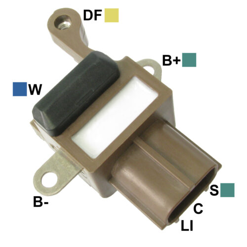

Voltage Regulator
GA124
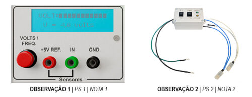
Test notes: Regulators with "DFM", "FR", "LI" terminal - regulator pulse output terminal to the vehicle's Electronic Control Unit to inform about the regulator’s functioning. To check its operation, use the sensors test module in the Frequency function. Using the PU02 cable set, connect the green tip to the "IN" input and the red tip to the "+ 5V REF" input, then connect the green alligator clip to the DFM, FR or LI terminal attached with the red alligator clip (+ 5V REF). Perform the regulator test and, during the test, the DFM (FR, LI) signal output frequency and the percentage of the time that the signal remains high should appear on the LCD screen of the sensors test module.Regulators with "D", "PWM" terminal - this regulator terminal is used by the vehicle's Electronic Control Unit to control the voltage set point. The Tester is supplied with a PD/PWM DRIVER that allows for testing this type of regulator by simulating the signal sent by the Electronic Control Unit to the regulator. To perform the test, follow the procedure below:• Connect the green cable of the DRIVER to the green cable of the regulator testing harness (RM01) and the black cable of the DRIVER to the black cable of the harness• Connect the white cable of the DRIVER to the "D" or "PWM" terminal of the regulator• If the regulator is a "PD" type, connect the blue cable of the DRIVER to the "P" terminal of the regulator• Connect the regulator testing harness (RM01) as indicated on the instructions and perform the test
Set Point: 14,25
