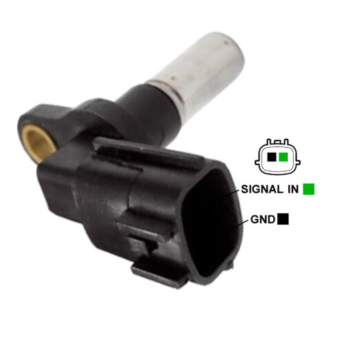

Crankshaft Position Sensor
GS8126
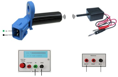
Test notes: This type of sensor has only two terminals, which are connected to an inductor that generates the voltage signals when varying the magnetic field. To perform the test, follow the procedure: 1. In the sensors test module, adjust the LCD display to show the frequency 2. Connect the sensors test cables (PU02) to the available “IN” and “GND” inputs below the LCD display and the smaller terminals on the sensor to be tested, as shown in the image 3. Connect the Auxiliary Coil (BA01) to the “R/EXT” and “NEG” inputs available on the coils test module. It will generate the magnetic field required for the sensor operation 4. Activate the “Modules/Coils” test module and bring the Auxiliary Coil tip closer to the speed sensor tip. The sensor will start generating the signal and the LCD display should show the value of the sensor operating frequency 5. The frequency can be changed between 50Hz and 400Hz by pressing the speed button on the “Modules/Coils” test module and, by changing the speed, the frequency shown on the LCD display must also vary
Order: - SIGNAL
