
Ignition Coil
GC4775
Number of outputs: 6
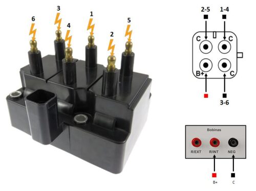
Test notes: In this coil, each pin “C” (coil) of the connector controls two high voltage outputs of the coil, therefore, the outputs must be tested in pairs, according to the numbers indicated in the image. To perform the test, follow the procedure below: • Connect one of the PU02 set cables between the “R/INT” output and the “B+” pin on the coil and the other cable between the “NEG” output and the “C” pin that controls a pair of coil outputs • Connect the high voltage cables from the equipment to the high voltage outputs of the coil, noting that the outputs are related to the connected input pin • Activate the Modules/Coils test section and observe the spark gap. There must be a spark in two electrodes, indicating the correct operation of the two outputs being tested • Disable the Modules/Coils test section and switch the “NEG” cable from one “C” pin to the other, which controls another pair of outputs. Switch the high voltage cables from the previous outputs to the new ones and repeat the test. Again, there must be a spark in both electrodes
