
Crankshaft Position Sensor
GS8324
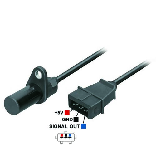
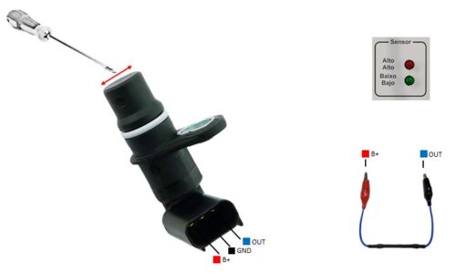
Test notes: This type of sensor requires a metal object or magnet to cross its magnetic field to produce a variation in output voltage.To perform the test, follow the procedure:1. Connect the modules test harness (RM02) to the sensor pins “B+”, “OUT” and “GND” as shown in the picture2. Connect the Auxiliary Resistance (RA01) between sensor pins “B+” and “OUT”3. Activate the “Modules/Coils” test module and observe the Red and Green LEDs in “SENSOR”4. Pass a metallic (iron) object quickly and constantly from side to side close to the sensor. The LEDs should alternately light on and off each time the object passes the sensor5. Some sensors may generate a very low voltage signal at the output, making visualization more difficult
Order: SIGNAL - +
